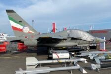


On the 22nd of April, Iran surprised the world by successfully launching the Noor satellite, using a previously unknown Satellite Launch Vehicle (SLV) which they call Qased.
The US Space Force confirmed that Noor reached orbit, together with a second object, assessed as the spent upper stage.
A detailed analysis of the Qased, based on open sources and using computer simulations to calculate trajectories, shows it has a strong relationship to the Shahab-3 ballistic missile Qasedand the Safir SLV, together with a number of unusual features for an SLV. If SLV compromises were removed, restoring the design optimization for use as a ballistic missile, the Qased can reach Central Europe and parts of Northern Europe, depending on its payload mass.
Iran’s previous satellite launch attempts have been notoriously unreliable. Last year a Safir SLV exploded on its launch pad and the much larger Simorgh SLV has never successfully placed a payload in orbit.
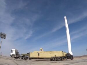
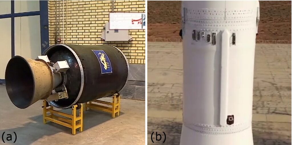
Figure 1: The Qased on its mobile erector launcher (Video still via Iranmedia.org)
As demonstrated in its ballistic missile attack against Al Asad airbase in January, Iran has made great leaps in improving the accuracy of its ballistic missiles, using maneuvrable re-entry vehicles with terminal guidance. Such a re-entry vehicle has also been tested on its Emad missile, with a stated maximum range of 1,700 km.
So far, Iran says it officially limits the maximum range of its ballistic missiles to 2,000 km; sufficient to reach Israel and Saudi Arabia, the stated foes of the Iranian regime. The US government maintains that Iran’s SLV development is a cover for building long-range ballistic missiles and this analysis does not contradict that assertion.
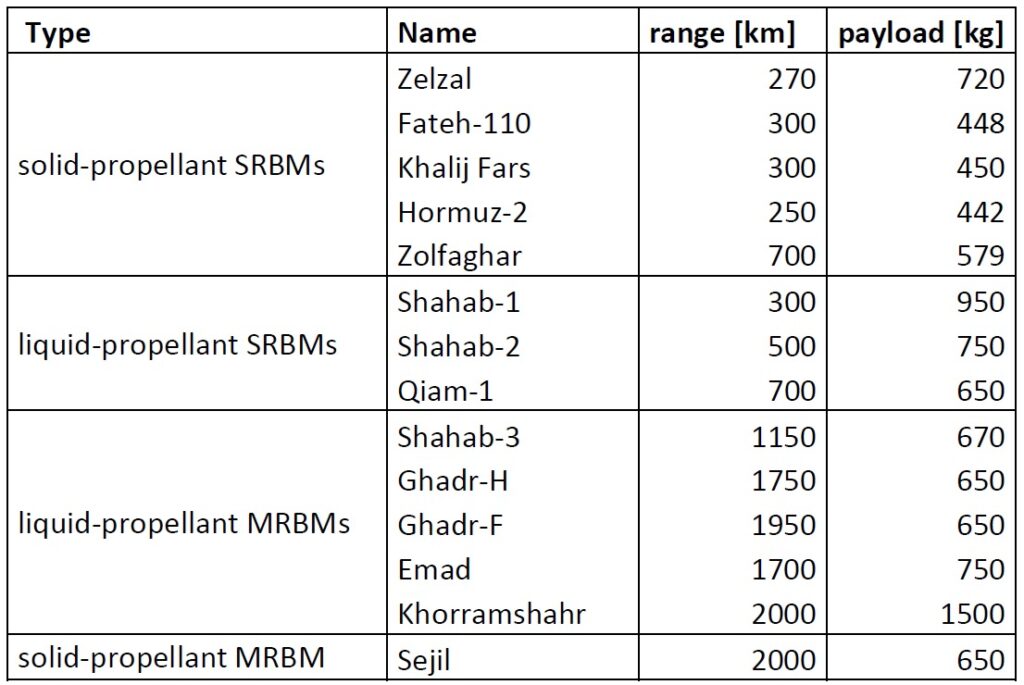
Table 1 lists payloads and ranges for Iran’s ballistic missile arsenal, as displayed in a recent Iranian TV documentary.
A booster optimized for launching satellites differs from a ballistic missile intended to deliver a warhead to a ground target, but much of the technology is similar. If it can accelerate a small satellite to orbital velocity (roughly 7.8 km/s for low-Earth orbit), it can also accelerate a heavier payload to the velocity necessary for sub-orbital trajectories to distances of more than 2,000 km (above 4 km/s). Iran first orbited a micro-satellite using an indigenously developed launch vehicle in 2009, with its Safir SLV. The larger Simorgh SLV was unveiled in 2010. Iran has followed the original model of the Soviet Union and the United States, by exploiting its ballistic missiles as a starting point for SLVs. Due to this close ancestry, restoring the Qased or Safir to their roots as ballistic missiles is a much easier path than continuing to a ‘pure’ SLV optimization.
The Safir and Qased use storable liquid propellants for their first stage (all stages for the Safir). The Safir and Simorgh upper stages use N2O4 oxidizer, which constrains storage and operations environments. Any military application would have to address the same issues that the US and Soviets encountered in the 1950s and 1960s. That’s what led to the use of silos. Iran apparently has stated that the Qased application of the Shahab-3 first stage is temporary and that they plan to introduce a solid rocket motor to replace it. Notable developments that would signal a ‘peaceful’ SLV effort would include the application of LOX cryogenic oxidizer with kerosene fuel (as done by SpaceX, for instance) for the upper stages, as this would offer significantly more thrust and overall power for the weight than the propellants now used. An SLV optimization would also include long burn times and the ability to stop and restart engines to apply thrust at the optimum position to maximize the mass delivered to orbit.
The Qased, shown in Figure 1, is smaller than the Safir and Simorgh and was transported and erected using a trailer practically identical to those used for Shahab-3 variants. The trailer’s obvious modification removes a bracket, because the Qased is longer than a regular Shahab-3. The Safir and Simorgh SLVs were developed under Iran’s (nominally) civilian space agency. However, the Qased, like the Shahab-3 that it is derived from, is the responsibility of Iran’s Islamic Republican Guard Corps, thus firmly establishing the link with Iran’s military ballistic missile program. This raises the question how the Qased could perform if it were restored to its roots as a ballistic missile.
Figure 2: Screens from inside a ground station showing a graph as a function of time (inset a) and trajectory parameters at 392.3s after launch (inset b). (Original video still via Iranmedia.org)
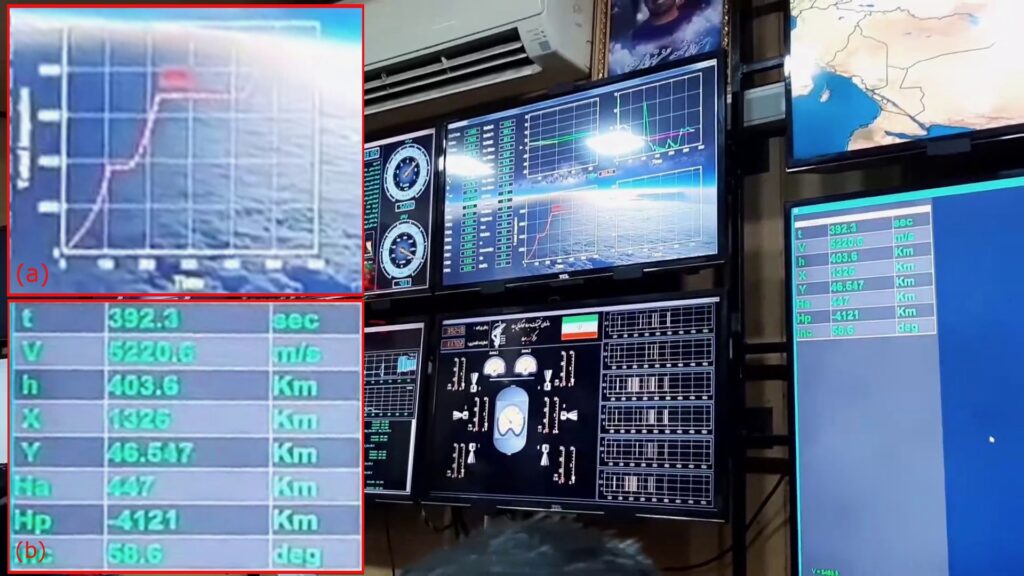
Iran’s media have released a wealth of photographs and video material of the missile and its launch. Figure 2 shows displays in a ground station. One of the displays shows a plot as a function of time (corrected for perspective and enlarged in inset a) that indicates that the missile has three stages and that, after burnout of each of the first two, the missile has coast phases. Another screen (inset b) shows trajectory parameters at 392.3 s into the flight.
Trajectory simulations were run against reverse-engineered data and releases using a medium-fidelity trajectory model to establish internally consistent values for unknown/uncertain missile parameters. This model was previously validated using publicly available information (the Atlas-F ICBM for sub-orbital trajectories and the US Minotaur I and the Chinese LM-3A for trajectories to orbit), which I’ve discussed in prior articles. Some of the missile’s parameters can be derived with reasonable accuracy from a closer look at the missile. After tuning the unknowns against the published material, well constrained values were obtained for the stages of the Qased, such that the simulation results in the correct satellite orbit, with parameters at 392.3 s that match the values visible on the screen. A reconstruction of the missile is shown in Figure 3.
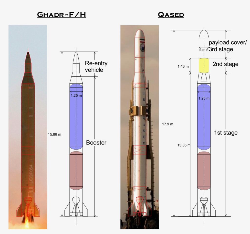
Figure 3: The Qased (right) SLV compared to the Ghadr-F/H (left), with the Qased first-stage diameter scaled to match. The arrangement of the Qased first-stage propellant tanks is notional; it is possible that the oxidizer tank (blue) is mounted below the fuel tank (red). (Original photographs: Reuters)
Iran has developed advanced Shahab-3 variants that use smaller and lighter tri-conic re-entry vehicles, smaller stabilising fins and lighter airframes. The Qased shares the small fins. At least two advanced versions of the Shahab-3, with placards denoting them as the Ghadr-F or Ghadr-H have the same overall length, but different tank lengths. This is clear from a difference in the lengths of cable raceways on the outside of the propellant tanks and seams in the outer skin, where the tank bulkheads are attached. The Iranian documentary that is the source for the information in Table 1 suggests that the Ghadr-H boasts a 1,750 km range and the Ghadr-F has a range of 1,950 km, which would indicate that the latter has the long tanks. In any case, the cable raceway in Figure 3, scaled such that the first stage diameter matches the 1.25 m diameter of the Ghadr, matches the cable raceway of the version with long tanks. The 1st stage parameters for the Qased simulation are derived from this tank size and Shahab-3 engine data from open sources.
The tank volume is consistent with the mass flow and the first stage burn time from the screenshot in Figure 2. Unlike the original Shahab-3, at least one of the advanced variants with long tanks has its oxidizer tank mounted in front of the propellant tank, as drawn in Figure 3, but Qased imagery is not clear enough to make sure it shares this arrangement. Visible differences between the Qased first stage and the Ghadr are limited to the paint scheme and to the top. The ballistic missile has a conical section that houses guidance equipment and serves as an adaptor for the re-entry vehicle. The Qased’s guidance system is likely placed in its upper stage and its conical section is longer and hollow. In the simulation, its mass and the mass of the payload fairing are included in the first stage deadweight, on the assumption that the fairing is discarded between stage 1 burnout and stage 2 ignition.
Figure 4: The Salman solid-propellant engine (a) and the Qased second stage (b). (Video stills from Iribmedia and Iranmedia.org)
Unlike its first stage, the Qased second stage is very different from that of the Safir. The Safir’s has the same 1.25 m diameter as its first stage and it uses liquid propellant, while the diameter of the Qased second stage is approximately 1 m (0.96 m). Video footage from an on-board camera that shows the stage separation also shows a fairly large nozzle, which protrudes into the conical section at the top of the booster. The shape of this second stage and its nozzle seem to match the Salman solid-propellant engine, which Iran unveiled earlier this year, shown in Figure 4. With a fairly typical density for solid-propellant, its size suggests a propellant mass of about 1000 kg. It steers through ‘thrust vector control’ accomplished by deflecting its nozzle with actuators.
There is less information on the third stage/ satellite kick engine, because it is hidden under a large payload cover. Due to glare on the screen in Figure 2, its burn time is also unclear. The only option for the simulations is to iteratively change the 3rd stage parameters such that the simulated trajectory matches the actual trajectory. The complete parameter set is listed in table 2.
Table 2: parameters of the Qased missile used in the simulation.
| Stage 1 | useful propellant mass [kg] | 14582 |
| deadweight factor incl. unused propellant [%] | 10.5 | |
| burn time [s] | 112 | |
| Isp sea level) [s] | 230 | |
| Isp (vacuum) [s] | 255 | |
| Stage 2 | duration of coast phase | 44 |
| useful propellant mass [kg] | 1000 | |
| deadweight factor incl. unused propellant [%] | 16.0 | |
| burn time [s] | 70 | |
| Isp (vacuum) [s] | 270 | |
| Stage 3 | duration of coast phase | 207 |
| useful propellant mass [kg] | 218 | |
| deadweight factor incl. unused propellant [%] | 39.8 | |
| burn time [s] | 54 | |
| Isp (vacuum) [s] | 270 | |
| Satellite | mass [kg] | 10 |
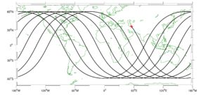
A specific impulse (Isp) of 270 s for the propellant is a moderate value for a solid propellant with a suitable vacuum expansion nozzle. The deadweight mass fraction (the mass of the stage at burnout as a percentage of the stage at lift-off) for the second stage is fairly typical for a relatively small solid-propellant engine. For the third stage it is significantly higher, because it probably houses the guidance equipment and thrusters for final course adjustments. The simulations do not allow a distinction between the dead-weight mass of the third stage and the payload mass, so the 10 kg satellite mass is an estimate. According to Gen. Jay Raymond, commander of the Space Force, Noor is a 3u cubesat, which would limit its mass to 4 kg. The computer program iteratively estimated the flight path angle as a function of flight time, such that the resulting satellite orbit matched the reported 444 km apogee and 425 km perigee altitudes. The simulated launch direction was chosen such that the inclination of the orbit matches the reported value of 59.8°. The ground track of the first eight simulated orbits is shown in Figure 5.
Figure 5: Simulated ground tracks of the Noor satellite. The red + shows the launch site near Shahroud (Visualization using the m_map software package and the Natural Earth database.)
A comparison between parameters on the simulated flight and those on the screen, in Figure 2, is shown in Table 3. The velocity and altitude are in exceptional agreement (less than 1 percent difference). The screen also displayed the apogee and perigee of the then-current trajectory. These can be calculated for the simulated ascent as well; the resulting values differ by only 1.3%. These results are quite sensitive to changes in the third-stage parameters. However, given engineering constraints, including “Occam’s Razor”, no other realistic parameter combination gave smaller residual differences with the reported parameters.
Table 3: Comparison between simulated trajectory parameters and screen values in Figure 2.
| variable | on screen | simulation | difference [%] |
| h [km] | 403.6 | 400.1 | -0.9 |
| V [m/s] | 5220.6 | 5190.3 | -0.6 |
| hapogee [km] | 447 | 453 | 1.3 |
| hperigee [km] | -4121 | -4173 | 1.2 |
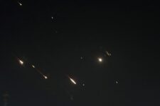
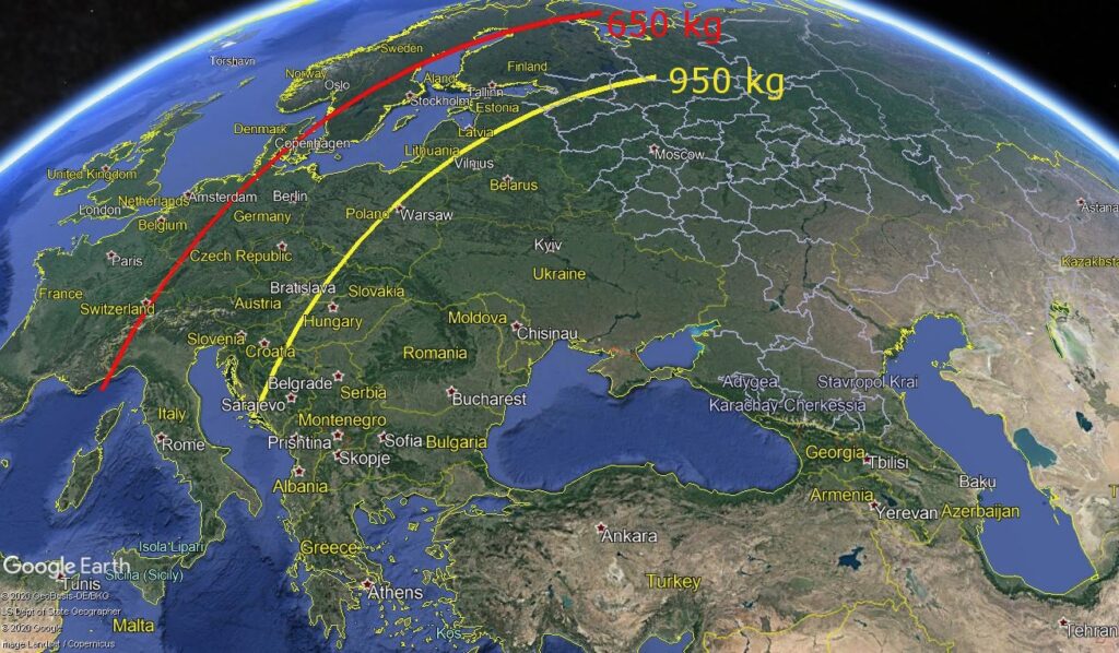
With these model parameters, we can now assess how this hardware would perform in a ballistic missile role. The clean modifications remove all mass above stage two, remove coast phases and emplace the warhead. The first-stage deadweight has been reduced, because the payload fairing is removed. The second-stage deadweight has been increased, to account for the addition of guidance equipment. On simulated maximum-range trajectories, with a payload of 650 kg, the range without Earth rotation is 3,337 km. This is reduced to 2,564 km with a 950 kg payload. The simulated maximum ranges on trajectories towards Europe, with a launch site in Northwest Iran and including Earth rotation, are shown in Figure 6.
With the heavier payload, much of Central and Eastern Europe is in range. With the smaller payload, the range is extended to include locations further to the west, including much of Germany and Italy, as well as parts of Northern Europe.
While it is by no means certain that the Qased is indeed intended as step towards a ballistic missile with a longer range than Iran’s current arsenal, these results show that it could be.
Ralph Savelsberg is an associate professor at the Netherlands Defence Academy, specializing in missile defense. This article does not reflect any official position or policy of the Government of the Netherlands. The author would like to thank James Kiessling for his valuable comments and suggestions.
A new approach to speed, scale and efficiency for the industrial base
Radars, EW, EO/IR, space imagery, and microelectronics are brought under one roof for a streamlined approach to common people and factories.
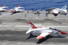
Navy jet trainer fleet operations remain paused after engine mishap
One week after the incident, a Navy spokesperson says the service is continuing to assess the fleet’s ability to safely resume flight.